


How to improve the linearity of AD75M1?
Oct 15, 2025
Leave a message
Hey there! As a supplier of the AD75M1, I've gotten a bunch of questions lately about how to improve its linearity. So, I thought I'd put together this blog post to share some tips and tricks that I've picked up over the years.
First off, let's talk about what linearity means in the context of the AD75M1. Linearity refers to how closely the output of the device follows a straight - line relationship with its input. In other words, if you increase the input signal by a certain amount, the output should increase by a proportional amount. A high - linearity AD75M1 is crucial for applications where accurate signal conversion is required, like in medical devices, industrial control systems, and high - end audio equipment.
1. Power Supply Considerations
One of the most important factors affecting the linearity of the AD75M1 is the power supply. A stable and clean power supply is essential. Fluctuations in the power supply voltage can introduce non - linearities in the output.
- Use a Low - Noise Power Supply: I'd recommend using a low - noise linear power supply instead of a switching power supply. Switching power supplies can generate a lot of electrical noise, which can couple into the AD75M1 and degrade its linearity. For example, a well - regulated linear power supply with a low output ripple (less than 10mV) can significantly improve the device's performance.
- Decoupling Capacitors: Place decoupling capacitors close to the power pins of the AD75M1. These capacitors help to filter out high - frequency noise and provide a local reservoir of charge. A good rule of thumb is to use a combination of ceramic capacitors (e.g., 0.1μF and 10μF) for different frequency ranges.
2. Input Signal Conditioning
The way you condition the input signal can also have a big impact on the linearity of the AD75M1.
- Filtering: Use appropriate filters to remove any unwanted noise or interference from the input signal. A low - pass filter can be particularly useful if your input signal has high - frequency components that are not relevant to your application. For instance, if you're working with a slow - changing analog signal, a simple RC low - pass filter can help to smooth out the signal and reduce noise.
- Amplification: If the input signal is too small, you may need to amplify it before feeding it into the AD75M1. However, make sure to use a high - linearity amplifier. A poor - quality amplifier can introduce its own non - linearities, which will then be passed on to the AD75M1.
3. PCB Layout
The printed circuit board (PCB) layout plays a vital role in maintaining the linearity of the AD75M1.
- Grounding: A proper grounding scheme is crucial. Use a single - point ground or a star - grounding topology to minimize ground loops. Ground loops can cause unwanted currents to flow, which can introduce non - linearities in the output. Make sure that the analog ground and digital ground are separated and then connected at a single point.
- Signal Routing: Keep the input and output signal traces as short as possible. Long traces can act as antennas and pick up electromagnetic interference. Also, keep the power supply traces away from the signal traces to prevent coupling of power - supply noise.
4. Temperature Management
Temperature can have a significant effect on the linearity of the AD75M1.
- Thermal Design: Ensure that the AD75M1 is properly cooled. High temperatures can cause the device's internal components to change their characteristics, leading to non - linearities. You can use heat sinks or fans if necessary, especially in applications where the device is expected to operate for long periods or in high - temperature environments.
- Temperature Compensation: Some advanced applications may require temperature compensation techniques. You can use a temperature sensor to measure the ambient temperature and then adjust the operation of the AD75M1 accordingly.
5. Calibration
Calibration is an effective way to improve the linearity of the AD75M1.
- Factory Calibration: Most AD75M1 devices come with some level of factory calibration. However, depending on your application requirements, you may need to perform additional calibration in - house. This can involve applying known input signals and measuring the corresponding output signals, and then adjusting the device's parameters to minimize the error.
- Regular Re - calibration: Over time, the characteristics of the AD75M1 may change due to factors like component aging and temperature variations. Therefore, it's a good idea to perform regular re - calibration to maintain its linearity.
Related Products
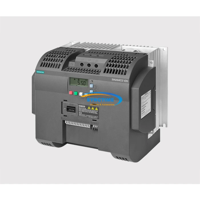
If you're involved in industrial control systems, you might also be interested in some other products. For example, the TS5214N530 OIH48 - 2500P8 - L6 - 5V Rotary Encoder is a great option for accurate position sensing. And the 6SL3210 - 5BE31 - 1UV0 Inverter 11kw can provide efficient power conversion for your machinery. Also, the 6SL3246 - 0BA22 - 1FA0 G120 Control Unit CU250S - 2 PN is a powerful control unit for industrial automation.
Conclusion
Improving the linearity of the AD75M1 requires a comprehensive approach that takes into account power supply, input signal conditioning, PCB layout, temperature management, and calibration. By following these tips, you can ensure that your AD75M1 performs at its best and provides accurate signal conversion for your applications.
If you're looking to purchase the AD75M1 or have any questions about improving its linearity, feel free to reach out. We're here to help you get the most out of this great device. Whether you're a small - scale hobbyist or a large - scale industrial manufacturer, we can provide you with the right solutions and support.

References
- Analog Devices Inc., "AD75M1 Data Sheet"
- Horowitz, P., & Hill, W., "The Art of Electronics"
- Johnson, H., & Graham, M., "High - Speed Digital Design: A Handbook of Black Magic"
Send Inquiry